

A high-rise booster system must overcome elevation, pipe friction and changing demand without overpressurising lower floors or making pumps start every few seconds. By the end, you will be able to trace the pressure cycle, check the key settings, estimate the design duty and identify the installation or fault most likely to cause unstable pressure.
Key takeaways
- Set pump cut-in and cut-out pressures within each building zone’s design limits.
- Use separate pressure zones when elevation creates excessive pressure differences between floors.
- Check vessel pre-charge, pressure sensors and non-return valves before blaming the pump.
- Install air chambers, slow-closing valves or surge control where water hammer persists.
How the pump, air vessel and controls create the pressure cycle
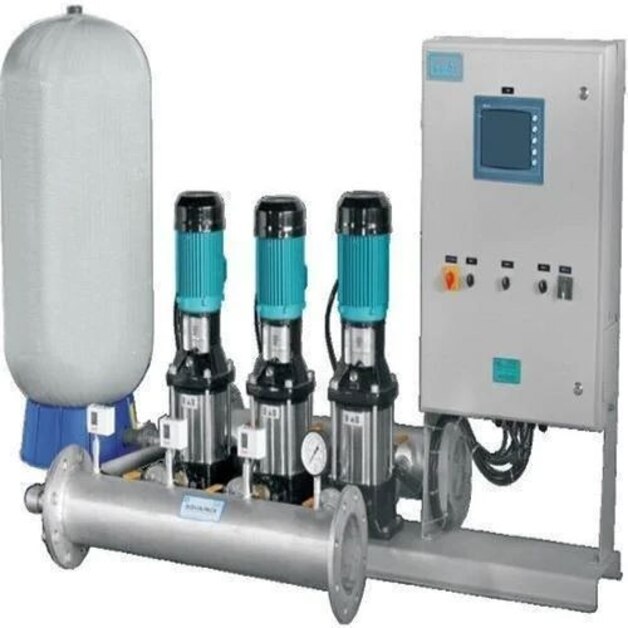
A hydro pneumatic water supply system runs through a pressure cycle. The pump delivers water into a pressure vessel, compressing trapped compressed air or nitrogen and storing energy. When a tap, shower or process fixture opens, expanding gas pushes stored water into the distribution pipe before the pump restarts.
As pressure reaches the cut-out setting, the pump stops; as demand lowers pressure to the cut-in pressure, it starts again.
- Pressure vessel: stores water and compressed gas, supplying short-duration flow between pump cycles.
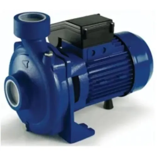
- Pump: provides the head needed to fill the vessel and serve the building.
- Pressure switch or pressure transmitter: senses discharge pressure and signals the controls.
- Non-return valve: stops pressurised water flowing back through the idle pump.
- Isolation valves: allow the pump, vessel and accessories to be serviced safely.
- Pressure gauge: displays local pressure for operation and fault checks.
- Relief valve: releases dangerous overpressure if controls fail.
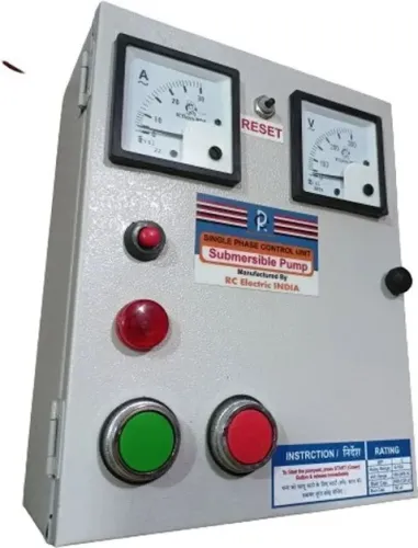
- Control panel: starts, stops and protects the pump, and manages alarms or standby changeover.
Cut-in pressure is the low setting that starts the pump. Cut-out pressure is the high setting that stops it. Pressure differential is the gap between those settings. Pre-charge is the gas pressure in an empty water-side bladder vessel.
For a compatible bladder tank, set pre-charge about 2 psi below cut-in with the water side isolated and depressurised. Follow the vessel manufacturer’s specification first. Nameplate volume is not usable drawdown volume; drawdown depends on settings, pre-charge, geometry and tank design.
How to size pressure and divide a high-rise into zones
Determine pump duty from the highest or most hydraulically remote fixture, then divide the building into zones when one pressure setting cannot serve every floor safely.
1. Measure the elevation from the pump discharge to that fixture. Add static head, pipe and fitting friction loss, the fixture’s required residual pressure while flowing, and a documented design margin. Water loses approximately 0.433 psi per vertical foot, or about 43 psi per 100 ft, so elevation quickly consumes available pressure.
2. Size flow for peak flow and calculated fixture demand, using fixture units, occupancy, expected simultaneous users and commercial process loads. Do not add every outlet at full flow; that produces an oversized pump, wasted energy and unstable control.
3. Select the duty point from the required flow and total pressure, then check the pump curve at that point. A 40–60 psi setting is not a universal answer. The final setting must satisfy the fixture minimum, elevation, friction loss, maximum downstream pressure and local authority requirements.
4. Divide the building into pressure zones when the pump pressure needed upstairs would overpressurise lower floors. Use separate booster zones, or install pressure-reducing valves on lower-floor branches with downstream relief protection.
5. Apply the International Plumbing Code trigger: distribution pressure above 80 psi requires pressure regulation. Verify static and flowing pressure at the booster discharge, lowest occupied zone and highest remote fixture; one pump gauge can miss a failed PRV or inadequate top-floor residual pressure.
How the system responds to low demand, peak demand and interruptions
At low demand, the pressure vessel supplies short-duration flow as compressed air or nitrogen expands. This drawdown delays the next pump start and reduces cycling. As demand rises, controls stage pumps: one starts first, additional units join at peak flow, and a duty-and-standby pump changeover transfers duty after a runtime, fault or failure.
Multiple pumps share the load instead of forcing one unit beyond its curve.
| Option | Pressure behaviour | Main limitation |
|---|---|---|
| Hydro-pneumatic start-stop | Vessel covers brief demand; pumps start at cut-in and stop at cut-out | Pressure swings across the differential |
| Overhead tank and gravity | Stored water supplies fixtures without pump operation | Pressure depends on tank elevation and falls on upper floors |
| Constant-speed booster | Pumps run at fixed speed and stage by pressure or flow | Larger pressure changes and more starts |
| Variable-frequency drive | Modulates speed to hold a target pressure | Needs correct sensing, calibration and tuning |
A variable-frequency drive holds tighter pressure only when its sensor is correctly located and calibrated and the drive is tuned to system volume and friction. A sensor beside the pumps can report good pressure while remote upper floors remain short, especially across separate pressure zones.
A power interruption stops pumps unless generator-backed controls are available. Automatic restart needs delay, low-suction-pressure protection, fault reset limits and a controlled sequence; it cannot promise uninterrupted service. One failed pump leaves reduced capacity unless standby equipment starts successfully.
Check these limits before increasing discharge pressure:
- Cavitation, air entrainment, blocked strainers and inadequate net positive suction head require suction-side correction.
- Direct boosting from a public main may require a break tank, air gap, backflow preventer or low-suction-pressure shutdown.
- Verify generator transfer, restart logic and standby capacity under the actual peak demand.
How to diagnose cycling, pressure hunting and water hammer
Rapid pump cycling usually means the vessel is not providing enough effective drawdown. Check for lost pre-charge, a waterlogged or ruptured bladder, an undersized vessel, or a pressure-switch differential that gives the pump too little run time.
1. Record pressure at the booster discharge, the lowest occupied zone, and the highest or most remote fixture or riser. Take both static and flowing readings with a calibrated pressure gauge. Compare the transmitter reading with the gauge; an inaccurate transmitter can cause pressure hunting or prevent the pump from reaching cut-out.
2. Inspect the field causes of unstable operation: a leaking check valve, plugged suction strainer, closed isolation valve, or incorrectly set pressure-reducing valve. Confirm the tank pre-charge with the water side isolated and depressurised, and test the bladder rather than assuming the nameplate volume equals usable drawdown.
3. Separate pressure hunting from water hammer. Hunting is repeated control correction or speed variation; water hammer is a pressure surge caused by rapid starts, abrupt VFD changes, closing solenoid valves, or defective check valves. Static pressure can look normal while these events damage joints and fixtures.
Check VFD ramp times, non-slam check valves, surge arrestors and air-release arrangements against pipe length, water velocity and valve-closure time. Do not select them from pump horsepower alone.
Sanas Engineering Khedshivapur can use these measurements to repair a pump, test controls or plan a temporary bypass. Matching flow and maximum pressure is unsafe: verify sensor range, suction conditions, motor starting current, potable-water requirements, check-valve compatibility and pressure-zone limits.
Related services
Hydro Pneumatic Water Supply System Hydro Pneumatic Water Supply System Sanas Engineering offers premium-quality Hydro Pneumatic Water Supply Systems designed to provide automatic, continuous, and energy-efficient water... View service → |
Booster Pumps Specifications Particular Details Product Name Booster Pumps Price ₹13,000 per Unit Minimum Order Quantity 1 Unit Product Type Pump Power Source... View service → |
What to verify before commissioning a commercial installation
A safe handover needs records that prove the booster can hold pressure without exceeding each zone’s limit.
Collect the pump curve with the marked duty point, pressure-vessel nameplate, pre-charge record, cut-in and cut-out settings, relief-valve set pressure, pressure-reducing-valve settings, control-panel sequence and zone schematic. For a bladder tank, record pre-charge with the water side isolated and depressurised; about 2 psi below cut-in is common, but the vessel manufacturer’s specification controls.
Test every pump in manual and automatic modes. Confirm non-return-valve direction, fully open isolation valves, and record static and flowing pressures at representative floors, including the lowest, highest and most remote outlets.
Verify approval for every potable-water contact material, including tanks, seals, coatings and pump components. NSF/ANSI/CAN 61 addresses health effects for drinking-water components; it does not prove hydraulic suitability or code compliance. Pressure regulation remains a separate design check, including the 80 psi International Plumbing Code trigger where adopted.
| Domestic booster | Supplies building fixtures | Use the approved domestic-water design |
|---|---|---|
| Fire pump | Serves fire protection | Design and commission under NFPA 20; a hydro-pneumatic booster is not a substitute |
Complete the commissioning checklist with:
- Alarm conditions and power-failure behaviour
- Standby-pump changeover and automatic restart
- Pre-charge inspection interval
- Maximum permitted pressure in every zone
Frequently asked questions
How does a hydro pneumatic water supply system maintain pressure?
The pump fills a pressure vessel and compresses its air or nitrogen charge. When fixtures open, expanding gas pushes stored water into the building pipework before the pump restarts.
How do you divide a high-rise building into pressure zones?
Divide the building when elevation causes unacceptable pressure differences. Size each zone from the required fixture pressure, static head, friction loss and pump shut-off pressure.
What causes pump cycling or pressure hunting?
Common causes include incorrect vessel pre-charge, an undersized pressure vessel, faulty pressure sensors, leaking check valves, blocked strainers or unstable control settings.
How can you reduce water hammer in a commercial water system?
Find rapidly closing valves, oversized pumps and sudden check-valve closure. Use correctly selected surge arresters, air chambers, slow-closing valves or variable-speed control.
What should you verify before commissioning the installation?
Confirm pipe pressure-test records, vessel pre-charge, pump rotation, relief-valve settings, sensor calibration, zone pressures, alarm functions and automatic restart behaviour.
Related service
Control Panel Sanas Engineering offers high-performance Electric Water Control Panels designed for efficient operation, monitoring, and protection of water pumping... View service → |