

A pump panel does more than switch a motor on and off: it interprets level signals, applies operating rules, and separates overload, short-circuit, phase, and earth-fault protection. By the end, you will be able to specify the panel, sensors, shutdown logic, installation conditions, and commissioning tests that your pump system requires.
Key takeaways
- Use float or level signals to trigger start and stop commands.
- Match contactors, overloads, breakers, and enclosure ratings to the motor.
- Define separate start, stop, high-level, low-level, and fault conditions.
- Test manual, automatic, alarm, overload, and emergency-stop functions before handover.
How a level signal becomes a pump command
An electric water control panel starts a pump by converting a changing water level into a switching command. A float signal changes state when water reaches its start point; the level controller operation checks that signal against the programmed conditions, then energises a control relay or contactor.
The contactor closes the motor circuit, supplying power to the pump.
- As the tank, sump, or wet well rises to the start level, the float or level sensor sends the run request.
- The controller applies any time delay and confirms that the system is in automatic mode, has control power, and has no active trip.
- The contactor pulls in, the motor starts, and the water level falls until it reaches the stop level.
The stop level must sit below the start level by a defined differential. Without that gap, a water pump control panel can chatter the contactor as waves move the float, causing repeated starts and motor heating. A short start delay also filters brief level changes; a long delay can allow overflow.
For two pumps, define lead and lag levels, a start and stop differential, and an alternation rule. Alternating the lead pump shares running hours, but it is not redundancy: one flooded enclosure, blocked discharge, failed control supply, or wrong level signal can disable both pumps.
A high-level float starts dewatering, while a separate low-level or dry-run input protects against lost suction or an empty wet well. One float cannot reliably perform both jobs.
What belongs inside the enclosure—and how it must match the motor
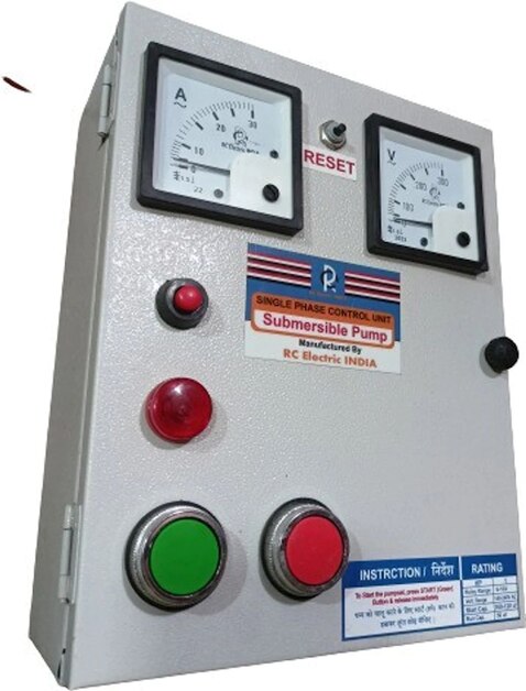
Safe switching requires devices matched to the motor’s phase, voltage, full-load current and starting current. An isolator or MCCB provides the main disconnect and short-circuit protection; fuses and MCBs protect control circuits and smaller branches. A contactor switches motor power, while an overload relay responds to sustained overcurrent and overheating.
It does not replace the branch-circuit short-circuit device or personnel ground-fault protection.
- Include phase-loss or phase-unbalance protection on three-phase motors; single phasing can overheat the remaining windings before an incorrectly set overload trips.
- Provide a control transformer when the control voltage differs from the supply, plus terminal blocks, selector switches, indicator lamps and an emergency stop where the installation requires one.
- Check motor rotation during commissioning. Wrong phase sequence can reverse many three-phase pumps.
| Motor or drive choice | Panel match | Risk if mismatched |
|---|---|---|
| Single-phase motor | Match rated voltage, full-load current, starting current and capacitor arrangement | The contactor or protective device can weld, trip repeatedly or fail to start the pump |
| Three-phase motor | Match phase voltage, motor full-load current, short-circuit rating and phase protection | Single phasing, excessive current or reversed rotation can damage the pump |
| Variable-frequency drive | Set permissible minimum speed, acceleration, deceleration and restart behaviour for the motor and pump | Low-speed cooling loss or unstable hydraulics can overheat the motor or pump |
Select the enclosure for the exposure: NEMA 3R covers outdoor rain, sleet, snow and external ice; NEMA 4 adds hose-directed water; NEMA 4X adds corrosion resistance. Neither rating permits immersion. On temporary construction sites, use GFCI protection for personnel receptacles unless an assured equipment-grounding conductor program is operated; an overload relay is not GFCI protection.
How to choose sensors and define the operating sequence
Specify the sensor against the liquid, vessel geometry and failure you need to detect—not simply the lowest purchase price. An open tank, borewell and slurry pit need different signals.
| Sensor | What it means | When it applies |
|---|---|---|
| float switch | Simple high or low discrete signal | Tanks, wet wells and dewatering pits with clean cable movement |
| electrode probe | Conductivity-based level contact | Conductive water with limited coating, fouling and mineral deposits |
| pressure switch | Switches at a set pressure, often indicating level indirectly | Pressurised systems or discharge-pressure protection |
| ultrasonic level sensor | Non-contact continuous level measurement | Open tanks where foam, condensation and poor reflections are controlled |
Electrode probes fail when water conductivity changes or deposits coat the tips. Ultrasonic readings fail over foam or an irregular surface; a pressure device fails when its sensing line blocks. Keep a separate high-level float for overflow protection and a low-level or dry-run input for loss of suction.
One float cannot reliably perform both jobs as pump geometry changes.
Define the sequence in the specification:
- Start at the high-level setpoint and stop at the low-level setpoint; state the differential in millimetres or pressure units.
- Add a start delay, stop delay and minimum run time to prevent rapid cycling.
- Alternate the lead pump after each completed cycle, then start the standby pump at a defined high-high level or after a timeout.
- Require flow, pressure or differential-pressure confirmation for dewatering and concrete-cutting slurry; overload protection alone will not detect every blocked or air-bound pump.
- Keep local alarms and protection active if telemetry fails, and define whether power restoration requires manual restart permission.
How the panel handles faults and site installation risks
A pump must stop locally when a dangerous condition appears; it must not depend on a cellular, radio, or Ethernet alarm. Keep the high-level alarm and pump protection active during communications failure, or a rising wet well can flood the site unnoticed.
Use separate protective responses for separate faults:
- An overload relay trips on sustained overcurrent and overheating. A fuse, MCB, or MCCB must clear a short circuit; the overload relay is not a substitute.
- Phase failure protection blocks or stops a three-phase motor during phase loss or severe phase unbalance. Check phase sequence during commissioning because reversed sequence can reverse pump rotation.
- Dry-run protection stops the pump when a low-level input, suction switch, or other approved device indicates loss of water. A high-water float starts dewatering; it cannot reliably protect against an empty wet well by itself.
- Ground-fault protection trips leakage current. For temporary construction sites, personnel-use receptacles need GFCI protection unless an assured equipment-grounding conductor program is in operation. Motor overload protection does not provide this function.
- A failed, broken, or shorted sensor cable should create a fault alarm and inhibit automatic starting rather than appear as a safe level.
- A flow switch or pressure signal should identify no-flow after starting and stop or alarm the pump according to the hydraulic design.
Motor-current dry-run logic is only indirect. Pump curve, liquid density, speed, and valve position change the current threshold, so pair it with a level or suction input where loss of water can damage the pump.
What to verify during selection, commissioning, and handover
Confirm the completed system by witnessing normal starts, controlled stops, faults, and power restoration; a motor running once proves very little. During selection, match the panel to motor full-load current, starting method, supply phase and voltage, pump count, enclosure location, and required IP rating.
Sanas Engineering Khedshivapur can help compare a panel design against the actual pump schedule, site conditions, and duty arrangement rather than a generic motor rating.
- Check that the isolator, short-circuit protective device, contactor, overload relay, and ground-fault protection are separately identified. An overload relay does not clear a high-energy short circuit or replace personnel GFCI protection on temporary-site receptacles.
- Run pump panel commissioning with the discharge path safe and the pump correctly primed. Verify rotation, phase-loss and phase-unbalance trips, overload settings, emergency stop operation, sensor failure response, and alarm indication.
- Test lead lag pump control by simulating rising and falling levels. Record the start and stop differentials, time delay, alternation rule, standby start sequence, and the result when one pump is unavailable.
- Prove that a blocked discharge, dry-run signal, float stuck in one position, broken level cable, or high-level condition produces the specified trip or alarm.
- Interrupt utility power, restore it, and test automatic restart separately in local and remote modes. Confirm whether restart requires an alarm acknowledgment or restart permission before rotating equipment energizes.
- At handover, obtain as-built drawings, setpoints, fault-reset instructions, test results, motor data, IP rating, and a clear list of who may reset or override protections.
A site operator should sign each witnessed result, not accept “tested OK” without the measured setting and observed response.
Related services
Control Panel Sanas Engineering offers high-performance Electric Water Control Panels designed for efficient operation, monitoring, and protection of water pumping... View service → |
Controller Sanas Engineering offers advanced Water Level Controllers designed for automatic monitoring, controlling, and maintaining water levels in overhead... View service → |
Frequently asked questions
How does a level signal start a pump?
A float or level sensor changes state at a set water level. The controller checks that signal and energises a relay or contactor when the programmed start conditions are met.
What must match between a control panel and pump motor?
The panel’s contactor, overload relay, breaker, cable terminals, and control circuit must suit the motor’s voltage, phase, full-load current, starting method, and rated power.
Which sensors can control an automatic water pump?
Common choices include float switches, electrode probes, pressure switches, ultrasonic level sensors, and hydrostatic level transmitters. Select one based on water quality, tank geometry, range, and required control accuracy.
How should pump control-panel faults be tested?
Test overload trips, phase loss, dry-run protection, high-level alarms, sensor failure, manual override, automatic restart behaviour, and emergency-stop operation before handover.