

Low pressure at an upper-floor tap does not automatically mean the building needs a larger pump. By checking the supply, measuring pressure and flow, calculating the duty point, and matching the pump arrangement to the building’s tanks and pressure zones, you can solve the actual restriction without over-pressurising lower floors.
Key takeaways
- Compare static and residual pressure at the entry and highest affected outlet.
- Calculate pump duty from flow, elevation, friction loss and required outlet pressure.
- Choose single, duplex or variable-speed pumps to match demand and tank layout.
- Set vessel pressure and outlet protection before commissioning the booster system.
Find the fault before you specify a booster pump
Reliable low water pressure diagnosis starts with two readings: static pressure with every outlet closed and residual pressure while a representative tap, shower, or hydrant flows. Record both at the building entry, a low-floor outlet, and the highest affected outlet.
A large static-to-flowing drop points to a closed isolation valve, blocked strainer, undersized pipe, leaking line, faulty pressure-reducing valve, or inadequate upstream supply—not automatically to a weak pump.
1. Confirm the symptom. Compare readings at several floors and at the incoming connection. If pressure is low everywhere, check the municipal supply, service pipe, meter, main isolation valve, and tank level. If only one branch or fixture is affected, inspect its valve, aerator, cartridge, airlock, and pipework. Ask whether blocked strainer filter repair?
is the actual remedy before ordering equipment.
2. Test under the same demand. Run one outlet, then several simultaneously, and measure flow with a calibrated meter or timed container. A sharp pressure collapse at the entry indicates limited supply capacity; a collapse after a filter, valve, or riser indicates a local restriction.
3. Check height before blaming the pump. Water loses about 0.098 bar per metre of elevation; a 30-metre rise consumes roughly 2.94 bar before friction losses. Measure from the proposed pump or tank water level to the highest outlet, then inspect suction conditions, including minimum tank level and pipe losses.
Low suction pressure can cause cavitation; increasing discharge pressure will not fix it.
Measure pressure, flow and elevation to calculate the duty point
A pump rated for maximum pressure will not tell you whether it suits the building. Measure the pressure at the inlet and at the highest or most remote outlet, both with no demand and while known fixtures are running. The difference between these readings shows how much pressure the existing system loses under flow.
Record the flow rate during the residual-pressure test. Use a calibrated flow meter, or collect a measured volume for a timed interval, then convert it to litres per minute. Size the design flow for the outlets expected to operate together, not for every outlet in the building.
Record these inputs:
- Static pressure at the incoming supply and residual pressure at the critical outlet
- Flow rate during the residual-pressure test
- Vertical elevation from the pump inlet water level to the highest outlet
- Pipe length, diameter, fittings, valves, filters and meters between the pump and that outlet
- Minimum pressure required at the critical fixture, such as a shower, process connection or filling valve
Elevation alone can consume the available pressure. Water loses about 0.098 bar, or 9.8 kPa, for every metre of rise. As a quick conversion, 10 metres water head is approximately 1 bar, or 100 kPa; a 30-metre rise therefore needs about 3 bar before friction losses.
Add elevation head, pipe and equipment losses, and the required terminal pressure. That total is the booster pump duty point: the design flow at the required discharge pressure. Select the pump to meet that point, not its advertised maximum flow or pressure.
Match the pump arrangement to tanks, floors and demand
A pressure-booster set should match the building’s pressure zones, tank levels and changing demand—not simply deliver the highest possible head. A single high-pressure pump can supply upper floors while over-pressurising lower-floor fixtures, valves and pipe joints.
| Option | Strength | Best fit |
|---|---|---|
| Fixed-speed booster | Simple controls; stages pumps as demand rises, but wastes energy through throttling at low demand | Steady commercial demand with defined pressure zones |
| Variable-frequency-drive booster | Adjusts speed to hold a setpoint and reduce excess head and power | Buildings with fluctuating demand and adequate control maintenance |
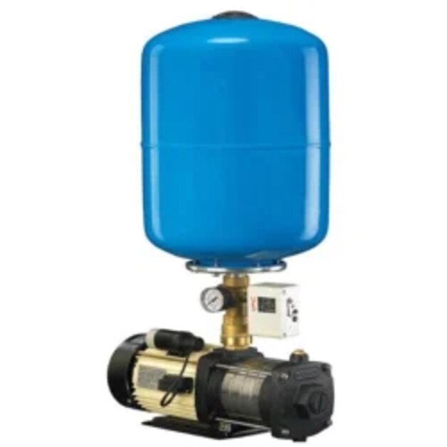
| Hydro-pneumatic system | Uses a pressurised vessel to reduce pump starts and smooth small draws | Intermittent demand where a compact installation matters |
| Rooftop tank with transfer pump | Stores water at elevation and supplies lower-pressure distribution by gravity | Buildings with reliable municipal filling and modest upper-floor demand |
Use an underground tank and transfer pump when the incoming supply lacks flow or cannot fill a rooftop tank reliably. Divide taller buildings into pressure zones, using separate booster stages, intermediate tanks or pressure-reducing valves so each zone receives only the head it needs.
A variable-frequency-drive booster saves energy only when its sensor represents the hydraulically critical remote riser or upper floor, not just the pump header. Protect every arrangement against minimum-flow overheating and short cycling with staged control, a small maintenance pump, bypass or controlled stop sequence.
Do not use a domestic booster as a fire pump; NFPA 20 duties require separately specified equipment and controls.
Install the pump where suction, controls and maintenance work
A good pump installation location is a dry, ventilated plant room beside the storage tank, with clear access to the motor, controls and valves. Keep the suction line short, straight and rising continuously toward the pump; high points trap air, while a narrow or obstructed line starves the impeller.
| Source arrangement | Installation requirement | Main risk |
|---|---|---|
| Break tank or cistern | Flooded suction, screened inlet, air gap and backflow protection | Tank starvation or contaminated supply |
| Public water main | Use direct connection only when the water authority permits it | Negative pressure and contamination of the main |
| Roof-level tank | Place the pump below the minimum tank-water level where possible | Insufficient suction pressure |
Calculate NPSHA at the lowest tank level, including suction-line losses, water temperature and supply pressure, then compare NPSHA with the pump’s NPSHR. If NPSHA falls below NPSHR, cavitation causes rattling, vibration, reduced flow and impeller damage; higher discharge pressure will not fix it.
Fit an isolation valve and accessible strainer on the suction side, and a non-return valve on discharge.
Put the pressure sensor on the common outlet after the non-return valve, where it measures building pressure rather than pump pulsation. Provide a bypass or minimum-flow route for low demand, and use a controlled stop or VFD ramp to limit water hammer.
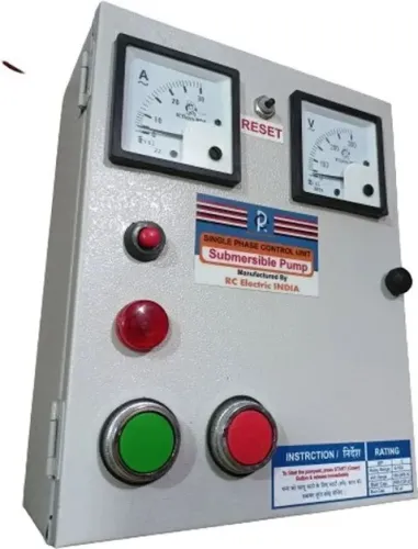
Protect the electrical supply against overload and dry running, and drain the plant room so a failed seal or pipe does not flood it.
Set vessel pressure and outlet protection for safe operation
Set pressure vessel sizing by usable drawdown, not the tank’s advertised volume. With the vessel isolated and water-side pressure at zero, set pre-charge pressure to the manufacturer’s value, commonly about 2 psi below the pump’s cut-in pressure.
Record the cut-in cut-out pressure settings and verify them with calibrated gauges; incorrect pre-charge leaves little drawdown and causes pump cycling.
Use a pressure vessel to absorb small demand changes, not to compensate for an undersized pump or missing storage tank. At low flow, configure a minimum-flow bypass, small pressure-maintenance pump or controlled stop sequence. A variable-frequency drive still needs these protections, because a running pump against a closed outlet can overheat.
Protect lower floors separately when the discharge needed at upper floors pushes static pressure beyond the plumbing limit. A pressure-reducing valve at a lower-floor zone, intermediate break tank or separate pressure zone prevents excessive pressure at fixtures.
The International Plumbing Code commonly uses 80 psi (552 kPa) as the maximum static water pressure; confirm the locally adopted code and water-authority rule. Add a pressure relief valve where the equipment manufacturer and code require it, but do not treat it as a substitute for pressure control.
For temporary service, define the bypass, isolation valves, relief path, minimum-flow route and shutdown contact before connecting a rental pump. Sanas Engineering Khedshivapur can help document these temporary settings so operators do not deadhead the pump or reconnect a high-pressure set to unprotected lower-floor pipework.
Related services
Booster Pumps Specifications Particular Details Product Name Booster Pumps Price ₹13,000 per Unit Minimum Order Quantity 1 Unit Product Type Pump Power Source... View service → |
Water Supply System Hydro Pneumatic Water Supply System Sanas Engineering offers high-quality Hydro Pneumatic Water Supply Systems designed to provide continuous, automatic, and energy-efficient water... View service → |
Frequently asked questions
What should you measure before specifying a booster pump?
Measure static pressure with outlets closed and residual pressure during flow at the building entry, a low-floor outlet and the highest affected outlet.
How do you calculate a booster pump duty point?
Combine required flow, elevation between supply and outlet, pipe friction losses and the pressure needed at the highest outlet.
Which booster pump arrangement suits a commercial building?
Match the arrangement to the tank layout, number of floors and demand pattern, using the appropriate single-pump, duty-standby or variable-speed setup.
Where should a booster pump be installed?
Install it where the suction pipe remains flooded, controls stay accessible, maintenance is possible and the pump has adequate protection from flooding.
What protections should be set on a booster pump?
Set vessel pressure correctly and provide outlet protection against excessive pressure, dry running, blocked discharge and unsafe operating conditions.