

A new slab, beam, wall, or foundation does not become part of an existing RCC structure simply because bars are drilled and bonded into it. You need a designed load path, verified reinforcement and services, controlled hole preparation, and installation records that prove the connection matches the design. By the end, you will know which connection method fits the extension, what information approval requires, and how drilling and anchoring should be controlled.
Key takeaways
- Verify the load path before choosing post-installed reinforcing bars.
- Locate existing reinforcement before drilling any RCC member.
- Control hole depth, bar spacing, edge distance, and adhesive installation.
- Inspect the connection before placing new concrete.
Choose the connection that matches the load path
Choose post-installed reinforcing bars for a structural extension when the engineer has verified development length, spacing, edge distance, adhesive capacity, and the existing member’s ability to carry the added forces. Do not select them simply because drilling is easier than exposing old reinforcement.
| Option | What it means | When it applies |
|---|---|---|
| Post-installed reinforcing bars | Drilled, cleaned, adhesive-anchored bars developed into existing concrete | New slabs, beams, walls, or footings where the layout and design checks fit |
| Exposed and lapped bars | Existing reinforcement is uncovered and connected with the required lap | Drawings and inspection confirm bar size, location, condition, and available lap length |
| Mechanical splice | A tested coupler joins existing and new reinforcement | A full lap will create congestion or cannot fit within the available member length |
| Separately supported connection | The extension carries its forces through new supports or foundations | The existing member, footing, or soil cannot safely accept the added demand |
A rebaring service can install post-installed reinforcing bars, but installation does not decide the load path. Check steel yielding or rupture, adhesive bond, pullout, concrete breakout, splitting, edge failure, and failure of the existing RCC member.
Define the new concrete connection for tension, shear, moment, or alignment. Dowel bars alone do not guarantee interface shear transfer; the design must address surface roughness, cohesion, friction, dowel action, and any shear key. Also check added dead, live, wind, seismic, and construction-stage loads on the old structure.
Survey the existing RCC member before marking holes
Before drilling, confirm the RCC member’s dimensions, concrete grade, reinforcement layout, condition, embedded services, and the forces the new connection must transfer. A successful scan does not prove that the existing beam, slab, column, wall, or footing can carry added dead, live, wind, seismic, or construction-stage loads.
1. Obtain structural drawings, repair records, and any earlier scan reports. Verify the member thickness, bar diameters and spacing, cover, lap or anchorage length, concrete strength, cracks, spalling, corrosion, and the proposed new concrete geometry.
2. Perform existing reinforcement detection with a rebar scanner. Use a cover meter to estimate bar position and concrete cover, then use GPR scanning where reinforcement is congested, layered, deep, or poorly represented by electromagnetic measurement.
3. Treat scan results as a map, not permission to drill. A cover meter can miss bars beyond its effective range or merge closely spaced bars; moisture, shallow cover, aggregate, and multiple layers can reduce GPR reliability. Use selective verification when the proposed hole is near a main bar, stirrup, tendon, conduit, or pipe.
4. Check for electrical conduits, plumbing, post-tensioning tendons, embedded plates, and previous anchors. Record uncertain zones and move the connection layout rather than cutting through them.
5. Have the engineer approve the final drilling grid against edge distance, bar spacing, development length, and the existing member’s capacity. Mark holes only after those checks are documented.
Control every hole, bar, and anchoring material
A post-installed bar is only as reliable as its hole, adhesive, and cure. Set the drill diameter and embedment depth from the engineered connection design, not from a rule such as ten bar diameters.
Use this controlled sequence:
- Mark the hole centre, angle, drill diameter, and embedment depth after locating existing reinforcement and services. Stop if the hole conflicts with either.
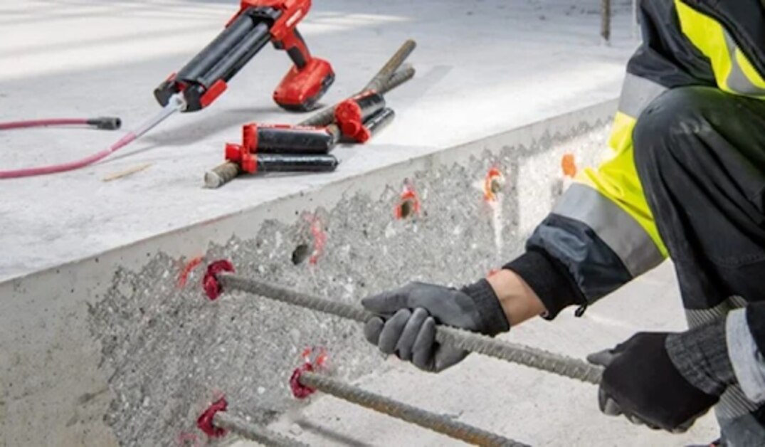
- Use diamond drilling or rotary-hammer drilling only when the adhesive manufacturer and design permit that method. Diamond drilling leaves a smooth wall that may need specified roughening; rotary-hammer drilling creates dust, vibration, and possible edge damage.
- Remove dust and slurry with the specified brush-and-blow sequence. Use the correct brush diameter, reach the full hole depth, and repeat until discharge is clean. A blocked pore or damp hole can reduce bond.
- Check the cartridge, nozzle, expiry date, storage condition, and approved temperature range. Inject from the back of the hole outward without trapping air, then insert the bar to the marked depth with the specified rotation.
- Keep the bar fixed while the adhesive cures. Do not load, vibrate, or connect reinforcement to it before the stated working and cure times at the actual concrete and air temperatures.
Record the hole diameter, depth, cleaning method, adhesive batch, bar size, insertion depth, and cure time. Reject and redesign nonconforming holes; do not hide them beneath new concrete.[curious]
Check the connection and the structure beyond the adhesive bond
Prove the connection from the new concrete through the bars, interface, existing member and its support—not through adhesive bond strength alone. Calculate the design tension, compression and shear forces before checking each possible failure mode.
- Verify steel yielding and rupture, adhesive bond, pullout, splitting, edge failure and concrete breakout.
- Confirm the bar’s development length for its diameter, grade, concrete strength, cover, spacing, cracking condition and anchoring system; do not substitute a “ten bar diameters” rule.
- Check the lap length where new bars splice to exposed existing reinforcement. Use a qualified mechanical splice or redesign the connection when congestion prevents the required lap.
- Check the old-to-new interface for shear transfer. Define the joint condition, remove laitance, specify the required surface roughness, and calculate cohesion, friction, dowel action and any shear key under the governing concrete design standard.
- Confirm that existing beams, slabs, walls, columns, foundations, supports and soil resist the added forces, including dead, live, wind, seismic and construction-stage loads.
Bars sized for tension can still leave the interface deficient in shear. A successful pullout calculation also does not prove that the existing member can carry the extension. Review reinforcement spacing, cover, edge distances and nearby openings against the proposed geometry, then document the governing limit state and the inspection evidence required before concrete placement.
Coordinate cutting, drilling, inspection, and concrete placement
An approved bar layout is not a work sequence. If cutting, drilling, and concrete placement are scheduled separately, crews can damage reinforcement, fill holes with slurry, or pour before inspection closes the connection.
1. Confirm the latest drawing, bar schedule, construction joint location, drilling method, anchoring product, hole depth, spacing, edge distance, and required cure time at the prestart meeting.
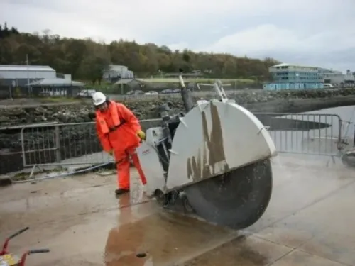
2. Survey the marked area with reinforcement scanning and service checks. Use concrete wall sawing with wet-cut capture or an approved vacuum system, then protect the drilling grid from slurry and uncontrolled dust.
3. Drill only within the approved grid. Record hole diameter, depth, drill type, operator, and any hit reinforcement or obstruction; do not move a hole without engineering approval.
4. Clean and inspect each hole before adhesive anchoring or cementitious grout anchoring. Record hole condition, product batch, temperature, injection sequence, bar insertion, and the time the connection becomes available for loading.
5. Keep the connection exposed for the specified inspection hold point. Check bar projection, alignment, spacing, and cleanliness before fixing forms and reinforcement, then place and compact concrete without displacing the bars.
Sanas Engineering Khedshivapur can be included in the work package when concrete cutting and rebaring records must come from one coordinated site operation. The engineer still signs off nonconforming holes and confirms that temporary works and the existing member can carry construction-stage loads.
Related service
Concrete Cutting Sanas Engineering provides professional Rebaring Services for structural reinforcement, concrete strengthening, repairs, retrofitting, and extension... View service → |
Frequently asked questions
How do you choose a rebar connection for a structural extension?
Match the connection to the load path after verifying development length, bar spacing, edge distance, adhesive capacity, and the existing member’s strength.
What must you survey before drilling an existing RCC member?
Locate existing reinforcement and embedded services, then mark hole positions only after checking member dimensions, cover, spacing, and edge distances.
Which details must be controlled during post-installed rebar installation?
Control the hole diameter, depth, cleanliness, bar size, embedment, spacing, edge distance, adhesive type, temperature range, and curing time.
What should you check beyond the adhesive bond?
Check steel strength, concrete breakout, splitting, pry-out, development length, load transfer, existing-member capacity, and the new concrete connection.